BDS-2120 airborne Beidou positioning and tracking equipment locates the aircraft in real time based on the Beidou positioning function, and periodically sends the obtained aircraft identification number, position, speed, time and other parameters to the ground platform using the short message function. It is the BDS airborne equipment that only realizes the aircraft tracking function. Aircraft parameters based on the output of the equipment shall not be displayed to the aircrew. Under normal circumstances, it cannot be used as the basis for air traffic controllers to implement air control decisions.
Product Functions
Support receiving Beidou B1I satellite signal, and calculate aircraft identification number, position information (longitude, latitude and altitude), ground speed, UTC time and other positioning information based on BDC coordinate system in real time through internal operation.
Support periodic transmission of location information, aircraft identification number, ground speed, UTC time and other data according to RDSS service agreement, and the transmission cycle shall not exceed 15min (short message transmission cycle can be configured).
Support receiving discrete magnitude suppression signal, actively suppress the sending function of short message, and restore the sending function of short message after the suppression signal is canceled.
Support receiving aircraft avionics data through ARINC429 Bus and sending avionics data to ground platform according to short message format.
Safety Level
Level E
Installation position
Beidou positioning communication antenna is preinstalled on the center line of the upper fuselage, outside the skin, where the lightning strike level is zone 2A. It is fixed on the aircraft skin through 4 connecting bolts (Part No. NAS1133-12, round head, maximum nail head diameter 9.6mm, screw diameter 4.83mm) and gaskets (outer diameter 11.6mm).
Airborne Beidou positioning and tracking transceiver:
Class E product: it is recommended to be installed at the position between the skin and diaphragm on the top of the cabin (constant pressure and temperature control area), and connected with the aircraft through 6 mounting holes.
Physical characteristics
Items | Descriptions | Parameters |
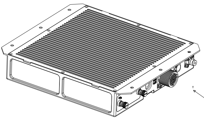
Overall Dimension | Dimensions of airborne Beidou positioning tracking transceiver | 265mm×227mm×47mm±0.5mm (L×W×H) |
Mounting hole pitches of airborne Beidou positioning tracking transceiver | 245mm×164mm±0.5mm (L×W) | |
Mounting hole aperture of airborne Beidou positioning tracking transceiver | 5.4±0.1mm | |
Dimensions of Beidou positioning communication antenna | 228mm×140mm×40mm±0.5mm (L×W×H) | |
Mounting hole pitches of Beidou positioning communication antenna | 129mm*69mm±0.5mm (L×W) | |
Mounting hole aperture of Beidou positioning communication antenna | 5.4±0.1mm | |
Weight | Airborne Beidou positioning tracking transceiver weight | ≤2.3kg |
Beidou positioning communication antenna weight | ≤1.5kg | |
Electrical Interface | Aircraft interface | 3 channel ARINC429 communication receiving interface |
3 channel discrete input interface | ||
Maintenance interface | 1 channel maintenance serial port, 1 channel Beidou serial port | |
RF interface | The RF interface is TNC. | |
System Power Consumption | Normal working condition | Voltage 28V, current ≤ 1A, power consumption ≤ 15W |
Launch condition | Voltage 28V, current ≤ 3A, power consumption ≤ 50W | |
Electrical Bonding | Airborne Beidou positioning tracking transceiver | Grounded through the grounding pile and 6 bolts, lap resistance < 5mΩ. |
Beidou positioning communication antenna | Grounded through 4 bolts, lap resistance < 5mΩ. |
Environmental characteristics
No. | Test Item | Test Subclass | According to DO-160G | Airborne Beidou Positioning Tracking Transceiver | Beidou Positioning Communication Antenna |
1 | Temperature altitude | Ground low temperature withstand test and low temperature short-time working test | 4.5.1 | A2/B2 | D2 |
Low temperature operation test | 4.5.2 | ||||
Ground high temperature withstand test and high temperature short-time working test | 4.5.3 | ||||
High temperature operation test | 4.5.4 | ||||
Altitude test | 4.6.1 | ||||
Decompression test | 4.6.2 | ||||
Normal pressure test | 4.6.3 | ||||
2 | Temperature variation | 5.3.1 | B | A | |
3 | Humidity | 6.3 | A | B | |
4 | Impact and falling impact | Work impact | 7.2 | B | B |
Crash safety | 7.3 | B | B | ||
5 | Vibration | 8.5.2 | S(C curve) | S(C curve) | |
7 | Explosive atmosphere | 9.0 | X | X | |
8 | Waterproof | 10.3.2 10.3.4 | W | S | |
9 | Fluid sensitivity | 11.4 | X | F | |
10 | Sand dust | 12.4/ 12.5 | X | S | |
11 | Mould | 13.5 | X | F | |
12 | Salt haze | 14.3.6.7 | X | T | |
13 | Magnetic effect | 15.3 | A | A | |
14 | Power input | Voltage (DC average) | 16.6.1.1 | AXI | X |
Pulsating voltage (DC) | 16.6.1.2 | ||||
Instantaneous power interruption (DC) test | 16.6.1.3 | ||||
Normal surge voltage (DC) | 16.6.1.4 | ||||
Voltage steady state (DC) | 16.6.2.1 | ||||
Instantaneous under-voltage operation (DC) | 16.6.2.3 | ||||
Abnormal surge voltage (DC) | 16.6.2.4 | ||||
Impulse current requirements | 16.7.5 | ||||
15 | Power spike | 17.4 | A | X | |
16 | Audio conduction sensitivity | 18.3 | Z | X | |
17 | Induction signal sensitivity | To the induced magnetic field in the equipment | 19.3.1 | CWE | ZCE |
To the induced electric field in the equipment | 19.3.2 | ||||
To the induced magnetic field in the interconnecting cables | 19.3.3 | ||||
To the induced electric field in the interconnecting cables | 19.3.4 | ||||
Inductive spikes in interconnecting cables | 19.3.5 | ||||
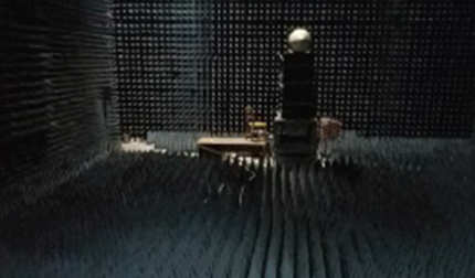
18 | RF sensitivity | 20.4 20.5 | R | R | |
19 | RF energy emission | 21.4 21.5 | M | Q | |
20 | lightning induction transient sensitivity | 22.5 | A3J3L3 | A3J3L3 | |
21 | Direct impact of lightning | 23.6 | X | 2A2A | |
22 | Freeze | 24.4.2 | X | C | |
23 | Static electricity | 25.5 | A | A | |
24 | Fire prevention and flammability | 26.5 26.6 | B | C | |
Other features
Mean Time Between Failure(MTBF)≥10000h
Mean Time to Repair(MTTR):≤0.5h